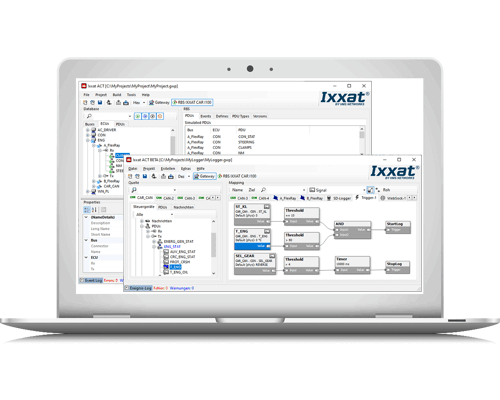
Automotive Configuration Tool (ACT) and the Embedded Platform provide the basis for a variety of inustrial and automotive solutions. The software is available in several bundles.
PC-software and run-time
The Advanced Configuration Tool (ACT) is a powerful and easy to use PC software package for Windows. The tool is used to create configurations for the CANnector and FRC-EP devices. After having created such a configuration, it is downloaded to the device and being executed there standalone. The configuration then runs as run-time on the hardware.
Saftware bundles and modules
Automotive Configuration Tool (ACT) is modular in design and is available with the following composition in three bundles:
| Standard | Lite | Free | |
| IxAdmin | |||
| Data Logger | |||
| Gateway | |||
| Development Tool | |||
| Visualisation | |||
| Matlab/Simulink & EtherCAT | |||
| Residual Bus Simulation (RBS) | |||
Functions & Modules
Detail overview of the available functions and modules:
ACT allows for many different configurations, but of course does not offer all possible functionality. In that case, a configuration can be extended with its own C user code. For some users, the development of C code is too complex or there are already finished models from other projects. The integration of these models is possible via an API based on the user code bus. Similar to the user code, a Matlab/Simulink model can then access the mapped signals/messages. DACT's RBS display provides a simulation environment for Electronic Control Units (ECUs) to test them independently from other network devices. Based on the FlexRay/CAN RBS and the XCPonEthernet extension, the signals sent by the RBS can be defined and manipulated. This includes, for example: The control of the signal manipulation can take place via user code, the gateway or XCPonEthernet. The gateway not only takes care of the data transfer from one CAN bus to another, but also makes it possible to connect "logical" bus systems - such as user code, data logger, Matlab / Simulink (option), etc. - with the overall data exchange . With this strategy it is possible to route each frame, PDU or signal from source to destination individually. This can be done directly or, for example, also via user code to manipulate the data on the fly.
This is possible by using the Gateway view of the ACT tool and using drag & drop to define the relationship between source and destination. Just drag the desired data from the source bus and drop it on the destination - irrelevant whether this is a real bus system or the user code, logger or something else. At the end, the created configuration can be loaded on an Ixxat embedded platform and run stand-alone. A bus description file can be provided for physical FlexRay, CAN and CAN FD bus systems. With the signal-based gateway, it is thereby possible to combine signals from different source messages into one target message. The FRC-EP and CANnector devices also provide analog or digital I/O ports. With ACT you can use these signals like any other signal in your configuration.
Ixxat’s Generic Ethernet protocol enables long-distance connections. Generic Ethernet is a virtual CAN (FD), FlexRay or LIN bus system on Ethernet. The desired data from / to the Generic Ethernet bus system can be mapped using ACT.
The data is then distributed over Ethernet and can be translated to the physical protocols using the CAN connector or FRC-EP series device. This is the classic range extender.
Up to 16 such virtual buses can be configured. This allows the desired data to be distributed not to one but to a maximum of 16 different IP addresses or ports. This makes it possible to create your own Ethernet-based communication network and simply use CAN (FD), FlexRay or LIN protocols on the last mile.
The Generic Ethernet protocol also allows the combination of Ixxat CAN @ net devices with CAN connector or FRC-EP series devices. This opens the possibility to expand up to a maximum of 136 CAN/72 CAN FD interfaces.
Administration tool for the embedded platform which is connected to the device via USB, Ethernet or Wi-Fi. Basis for most solutions are bus descriptions in CANdB, FIBEX or AUTOSAR-XML format. The descriptions contain a great deal of information, but often not all required information. Using the Vehicle Editor, everything that belongs to a certain vehicle, an integration level or a test configuration can be easily combined.Signal visualization
Development tool (UserCode)
An Eclipse-based development environment is available for the development of your own applications. Using this development environment, user code can be created for the extension of an ACT solution or for completely separate applications. ACT generates a C user code template that contains all the API to connect functions to the rest of the system. This is supported by the integration into the ACT project, the handy editor, cross compiler, as well as a high-level language debugger. The developed applications can be run stand-alone or on the Ixxat embedded systems. Functional models
Residual Bus Simulation (RBS)
Our RBS is automatically generated using a vehicle description database defined with the integrated vehicle editor . Select the desired ECUs) and ACT builds the configuration:
XCPonEthernet
HIL signaal manipulation
Gateway
FlexRay, CAN & CAN FD
Analog & digital I/O
After configuring the data direction, range of values, conversion rules and units, the I / Os can be mapped easily via drag & amp; drop. This makes it possible to map trigger inputs/outputs of the logger or to fill in vehicle signals based on analog inputs.
Bridging
For the connection of the data stream directly to a PC, the VCI driver can be used to use the device as an external PC interface. The Generic Ethernet protocol is very easy to implement on any target operating system via a communication script.
IxAdmin
Vehicle Editor


