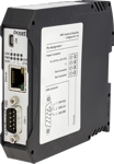
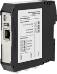
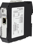
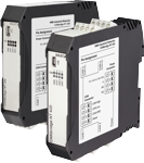
CAN Bridge NT 200/420
Configurable 2x/4x CAN-to-CAN Bridge and Router with CAN FD support
Both devices allow the easy coupling of CAN (CAN FD) networks, including networks with different bit rates or frame formats (11/29 bit identifier). The bridges/routers have a powerful microcontroller that can perform message filtering, ID translation and data multiplexing (e.g. required for CAN FD to CAN message conversion), at this even bursts at higher data rates can be processed without message loss.
Features and benefits
- Up to 4 CAN (2 CAN FD) channels in one device
- Powerful filter, ID translation, data mapping and multiplex functionality (NT 420)
- Action Rules and Cyclic transmission
- Easy configuration using a Windows-based tool, via USB
- Easy coupling of CAN and CAN FD systems and devices
- Cost savings due to simple wiring
- Allows system expansion and tree/star topologies
- Increased system reliability
- Line protection by galvanic isolation
CAN Bridging and Routering
Unlike a CAN Repeater, which only translates the electric signals, the CAN messages are received completely by the CANbridge NT and then sent to the other CAN or CAN FD network in line with existing filter, conversion, port mapping or multiplex rules (Store-Forward principle). By using mapping tables the message reception/transmission is possible between all 4 channels.
With the aid of filter and conversion rules, CAN or CAN FD messages can be filtered or modified. With these mechanism, the bus load can be reduced in the individual networks by only sending messages which are of interest to the other network. Data multiplexing allows the mapping of e.g. CAN FD frame data into several standard CAN messages.
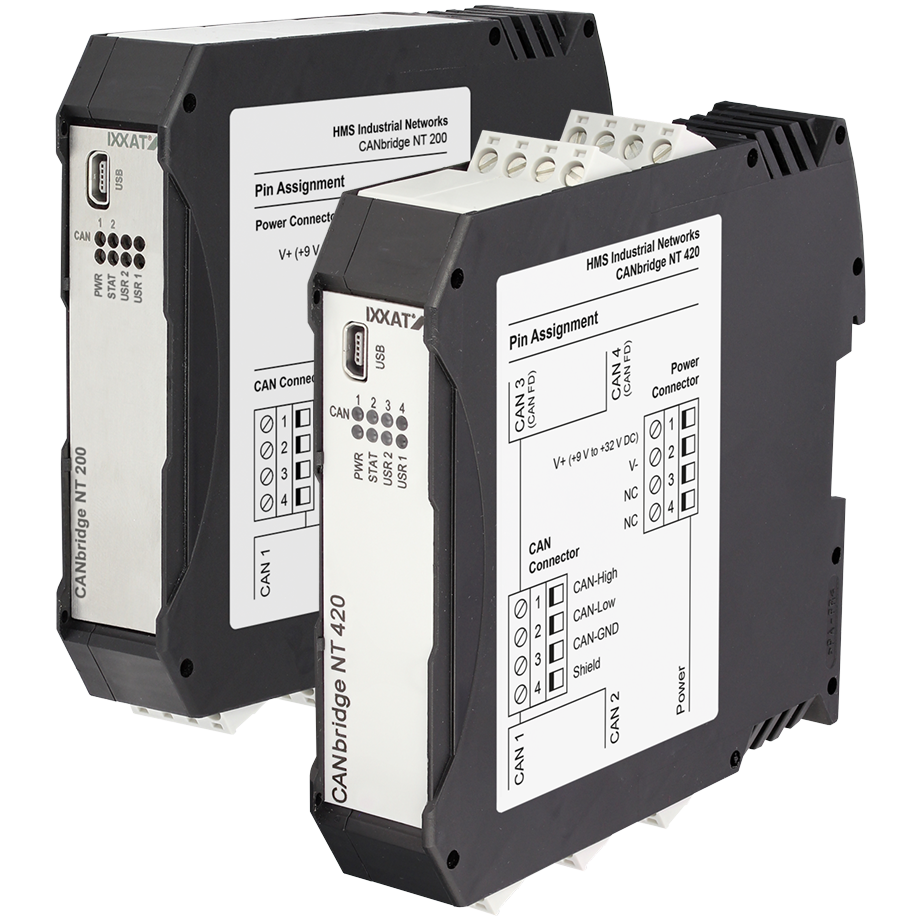
CAN Bridge NT 200
This device has two standard CAN channels. The bridge and router supports message ID filtering (value or mask), baud rate conversion, 11/29 bit frame conversion, message id conversion.
CAN Bridge NT 420
This device has four standard CAN channels, two of which can be switched to CAN FD. The bridge and router supports the same functionality as the NT 200, and features port mapping and data multiplexing in addition.
Filtering and multiplexing
By using mapping tables the message reception/transmission is possible between all 4 channels. With the aid of filter and conversion rules, CAN or CAN FD messages can be filtered or modified. With these mechanism, the bus load can be reduced in the individual networks by only sending messages which are of interest to the other network. For SAE J1939 applications a special mapping table is provided, adapted to the specific parameters.
The data multiplexing/demultiplexing functionality enables the mapping of e.g. CAN-FD data to several standard CAN messages and vice versa (NT420).
Action Rules
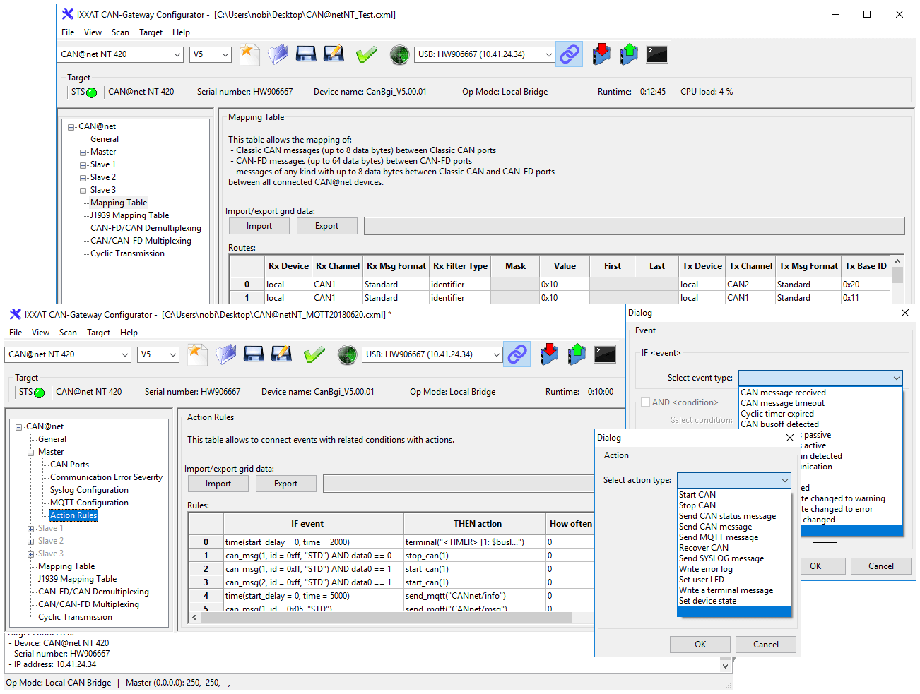
In response to received messages, device or CAN bus status events, a variety of actions can be performed automatically, e.g. sending messages (CAN, CAN FD), changing device settings or switching device LEDs. Action rules are created through intuitive drop-down menus for events and actions within the Windows-based device configuration tool.
Cyclic transmission
The cyclic transmission feature enables cyclic forwarding of messages. Both, messages and cycle times are defined within a central cyclic transmission table.
Status message
For diagnosis and error handling, the CANbridge NT can send a status message via CAN if required. For each CAN channel the status is reported whether it is Active, Error, Bus Off or Not available.
Configuration and firmware update
Using an easy to operate Windows configuration tool, the CANbrdige NT can be configured and firmware updates can be performed via an USB interface. With the tool, the configuration of filter, mapping, multiplexer or translation rules can be carried out very easily, without programming skills.
With the help of mapping tables, the exchange of messages between all channels can be configured very flexibly. Filter and conversion rules can be applied to the CAN and CAN FD messages. As a result, the bus load in the individual networks can be reduced since only relevant messages are transmitted to the other network.
The data multiplexing functionality enables the mapping of e.g. CAN-FD data to several standard CAN messages.
| Technical specifications | |
| CAN-bus tranceiver | Texas Instruments SN65HVD251P |
| CAN bus nodes | Max. 120 |
| CAN-bus termination | None |
| CAN baudrates | Standard CAN: 5 to 1000 kBaud CAN-FD: 5 to 8000 kBaud |
| Power supply | 9-36 V DC |
| Curremt consumption | 110 mA typisch @ 24 Volt voeding |
| Temperature range | Operating temperature -40 ºC ... +85 ºC |
| Storage temperature -40 ºC ... +85 ºC | |
| Galvanic isolation | 1 kV for 1 sec. |
| Certification | CE, FCC |
| Housing | Polyamide housing for top hat rail mounting |
| Protection class | IP20 |
| Size | Approx. 114,5 x 99 x 22,5 mm |
| Weight | Approx. 150g |
| Contents of delivery |
| - CANbridge NT |
| - Configuration software for Windows™ |
| - Configuration cable (USB) |
| - User Manual |
Part number(s)
